CLT (Cross Laminated Timber) structures in NextFEM Designer, analytically obtaining the resistance of the connectors
In the previous article we saw how to build the finite element model for the analysis of X- Lam structures , made up of shell walls and springs for connectors such as hold -down and tie -down, angles and screws.
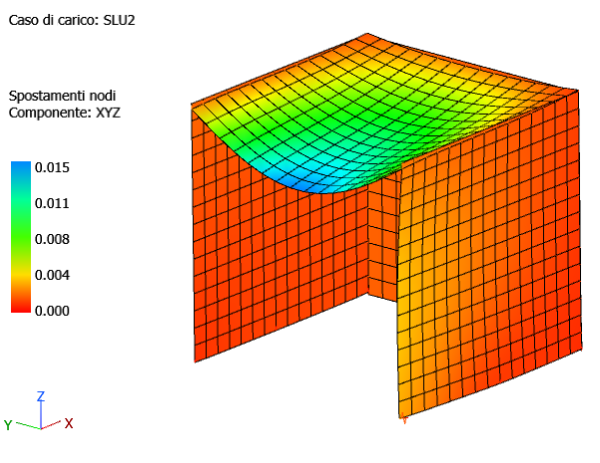
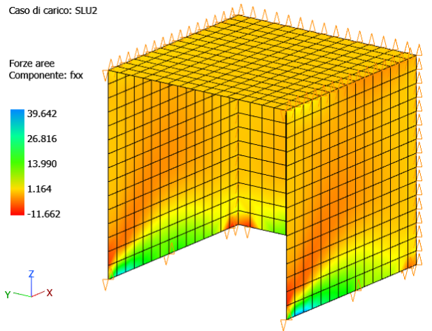
The results of the analysis of the model used previously can be consulted in terms of nodal displacements and forces and moments per unit length for the shells.
The verification of the X- Lam walls is immediate with the WoodCheck module : by selecting the item “All sections cut ” you can check for sections cut that were automatically defined for each wall by the mesher.
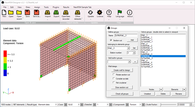
Let's see for example how the checks of the sections extreme cuts of the floor wall are not satisfied, in this case due to shear due to the rolling of the fibers for the group of elements Wall__3 (floor).
For floor panels it is advisable to check that the sections cut are positioned along the most stressed sections. If it is necessary to change them, sections can be generated cut in the orthogonal direction, replacing the default ones, from the “Create wall for design” command with the “Rotate section cut” inside the “Groups” mask.
The results of the connections instead consist of the forces that pass through the inserted springs, in the degrees of freedom that have a non-zero stiffness. Following the approach suggested in the previous article, we will find, for example, an axial force in the hold -downs and a cutting force for the corners.
Hold -down tension in correspondence with Vz (global Z), and the cuts in the plane in N and Vy , respectively for the global X and Y directions, are depicted in the following figure.
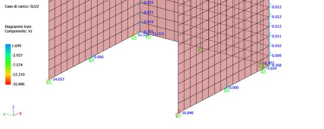
For hold -downs, for example, negative values indicate compression (therefore the spring is representing the contact of the wall with the foundation or with the underlying panel). We will therefore verify the tensile values of the hold -downs, the resistance of which is estimated once again on the basis of the Eurocode 5 indications as the connection between wood (the panel) and steel (the perforated plate of the hold -down).
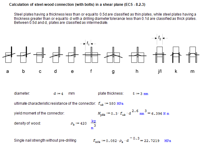
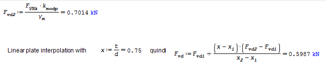
Below is an example of calculating the resistance on the wood-steel connection side of a screw, according to the formulation of Eurocode 5, which takes up the one originally proposed by Johansen .
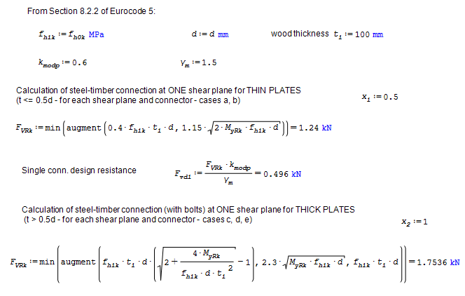
Considering for example 8 effective nails, we will have a resistance for a single hold -down equal to almost 5kN.
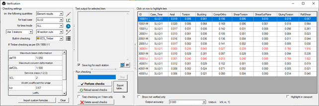
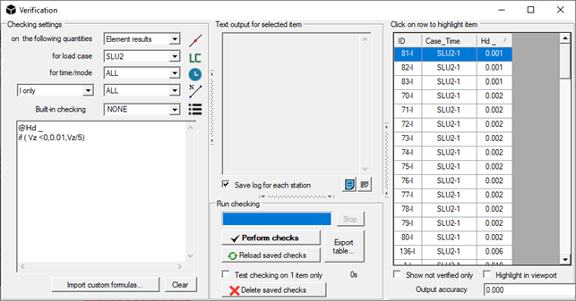
We can carry out the verification by selecting the hold -downs and setting the verification as shown in the following image.
We ask the verification engine to calculate the Demand/Capacity ratio (force Vz = hold -down pull / resistance equal to 5kN) and to show it in the " Hd " column . Thus lines with D/C ratios > 1 are highlighted in red. We conventionally assign a D/C ratio = 0.01 to the HDs in compression.
@Hd _
if ( Vz <0,0.01,Vz/5)
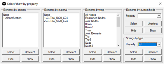
It is possible to repeat this procedure for each type of spring, selecting them by type from the View / Select by ... / Properties form or ALT+J (available from v. 1.9.1.3).
Conclusions
The method described allows the analysis and verification of CLT structures , including connectors. NextFEM Designer's mesh management capabilities allow you to easily create walls and springs. The verification of the CLT walls is carried out through the sections cut with built -in checks . Finally, the customizable verification engine allows you to carry out checks on connectors based on resistance assessments carried out according to Eurocode 5.
In CLT structures , the rocking of the walls is always non-linear, because it involves unilateral contact for the part in compression. The approximation that the linear analysis introduces could require in some cases additional analyses, carried out in particular conditions (e.g. wind in the +X direction) conventionally increasing the stiffness of the hold-downs in compression to a very high value, suitable for simulating the stiffness of the monolateral contact between the wall and the underlying surface.
The free spreadsheet available at the bottom of the article allows the evaluation of the resistance for nailed joints such as corners and hold-downs. Customized analysis and verification of connectors are always free operations with the basic version of NextFEM Designer.
Download the free resources! The files are editable with SMath Studio :
Calculation of the resistance of metal connections for X- Lam
NextFEM Designer also supports native interfacing with SMath Studio via the NextFEM4SMath plugin .