2.6. Draw menu
![]() Node: Inserts nodes in the model, after a working plane is selected.
Node: Inserts nodes in the model, after a working plane is selected.
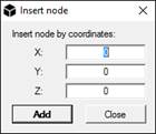
![]() Node by coordinates: Inserts nodes by coordinates. To insert a nodes by coordinates, insert them on the textboxes and then click on the Add button. It is possible to insert nodes until the Close button is pressed.
Node by coordinates: Inserts nodes by coordinates. To insert a nodes by coordinates, insert them on the textboxes and then click on the Add button. It is possible to insert nodes until the Close button is pressed.
![]() Truss: Inserts truss elements between two nodes. This element can react only in tension or compression.
Truss: Inserts truss elements between two nodes. This element can react only in tension or compression.
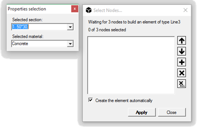
![]() Beam: Inserts beam elements between two nodes. To insert a beam element select a section and a material from , if it has already been defined, from Selected section drop-down menu in the Section selection window and then click on the nodes to be connected. Once finished click on the Close button in the Selected nodes window.
Beam: Inserts beam elements between two nodes. To insert a beam element select a section and a material from , if it has already been defined, from Selected section drop-down menu in the Section selection window and then click on the nodes to be connected. Once finished click on the Close button in the Selected nodes window.
![]() Beam3: Inserts a 3 nodes beam elements. The three nodes must be aligned.
Beam3: Inserts a 3 nodes beam elements. The three nodes must be aligned.
![]() Triangle: Creates a 3 nodes triangular plane element.
Triangle: Creates a 3 nodes triangular plane element.
![]() Triangle6: Creates a 6 nodes triangular plane element.
Triangle6: Creates a 6 nodes triangular plane element.
![]() WARNING: Triangle6 elements are transformed in a group of 3 nodes elements with the default solver.
WARNING: Triangle6 elements are transformed in a group of 3 nodes elements with the default solver.
![]() Quad: Creates a four nodes quadrilateral plane element.
Quad: Creates a four nodes quadrilateral plane element.
![]() Quad8: Creates an eight nodes quadrilateral plane element.
Quad8: Creates an eight nodes quadrilateral plane element.
![]() WARNING: Triangle6 elements are transformed in a group of 3 nodes elements with the default solver.
WARNING: Triangle6 elements are transformed in a group of 3 nodes elements with the default solver.
![]() Tetra: Creates a 4 nodes tetrahedron.
Tetra: Creates a 4 nodes tetrahedron.
![]() Tetra10: Creates a 10 nodes second-order tetrahedron.
Tetra10: Creates a 10 nodes second-order tetrahedron.
![]() Wedge: Creates a 6 nodes wedge.
Wedge: Creates a 6 nodes wedge.
![]() Wedge15: Creates a 15 nodes wedge.
Wedge15: Creates a 15 nodes wedge.
![]() Hexa: Create an 8 nodes hexahedral element.
Hexa: Create an 8 nodes hexahedral element.
![]() Hexa16: Create a 16 nodes hexahedral element.
Hexa16: Create a 16 nodes hexahedral element.
![]() Hexa20: Create a 20 nodes hexahedral element.
Hexa20: Create a 20 nodes hexahedral element.
![]() Spring: Creates a 2 nodes spring.
Spring: Creates a 2 nodes spring.
![]() WARNING: To create a spring element, the spring properties must be specified in Assign/Spring properties and then assigned to the element.
WARNING: To create a spring element, the spring properties must be specified in Assign/Spring properties and then assigned to the element.
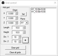
![]() Grid manager: it manages all grids in the viewport, to support drawing nodes. In grids, at each line intersection, snap is available.
Grid manager: it manages all grids in the viewport, to support drawing nodes. In grids, at each line intersection, snap is available.
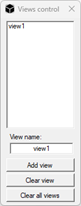
![]() Views control: it creates and handles model views.
Views control: it creates and handles model views.