Strength calculator
By the Strength calculator button it is possible to define the rebar in a RC section and to evaluate its flexural strength.
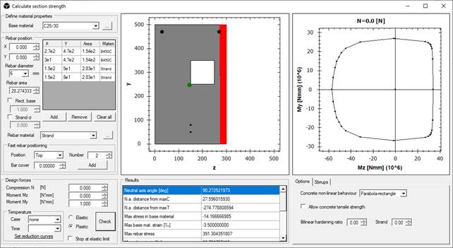
In Define material properties the base material is specified.
The box Rebar position can be used to specify the rebar coordinates (eventually of rectangular shape by checking the option Rect. rebar and by specifying the base dimension of the plate in Rect. base). The rebar coordinates are input on the base of the section local coordinate system, by specifying the diameter and the associated material (that can be set or added by the command “…”). The available materials should be customized by modifying or adding *.nfm files in data/design subfolder in the software installation directory.
In order to insert strands for prestressed RC sections, it is possible to input the initial strand stress by activating the Strand s option and by inputting the stress in consistent dimensions.
To obtain the resistant values of the section, specify the Design forces in the required units. By selecting the Elastic option, the response of the section is computed with elastic materials. By selecting Plastic, elastic-perfectly plastic laws are used for material behaviour. In the Results box, the results of the performed computation are reported, linked to the overlying graphs.
The window allows also resistant domains calculations reduced by thermal action. The software will compute the strengths parameters of the section at the selected instant of time and thermal case, on the base of strengths reductions laws for mechanical and resistant features of base material and rebar, if present.
The available options in this mask are:
- Concrete non-linear behaviour allows to choose between parabola-rectangle and bilinear material behaviour for the concrete material. If a simple rectangular or circular section are present, the Confined concrete option is available in this menu, allowing to consider the confined part of the section inside stirrups. In this case, data in Stirrups tab are required. Spirals are not supported.
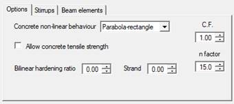
- Allow concrete tensile strength can be enabled to activate the contribution of tensile strength of the base material;
- Bilinear hardening ratio allows to specify the ratio between the plastic branch of rebar and their elastic modulus. In case of Steel or Aluminium base material, it specifies the hardening ratio to be used.
- Steel class section sets the class of the section in case of Steel or Aluminium base material, i.e. if the section can be calculated in plastic field or not.
- Confidence Factor (C.F.) sets the confidence factor for strength of base material and rebar.
- n factor specifies the value of the homogenization factor (modular ratio between steel and concrete). The default is 15.
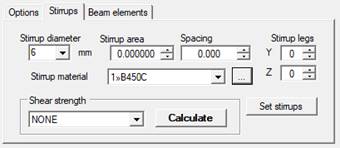
Stirrups tab helps to define the stirrups for the current section and to obtain a resisting strength for both direction of the section.
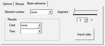
Beam elements allows to retrieve the rebar defined for a beam to check its strength over the beam forces contained in results, if available.
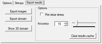
Export results contains options to plot rebar stresses after analysis and to customize calculation accuracy, plus some commands to save section images, export strength domain or show 3D domain.
![]() Load cases: Inserts the linear static load cases by writing the Name box and then clicking on the Add button. Different load can be inserted without closing the Set load cases window.
Load cases: Inserts the linear static load cases by writing the Name box and then clicking on the Add button. Different load can be inserted without closing the Set load cases window.
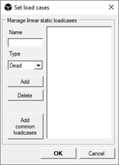
![]() WARNING: only linear static load cases can be inputted from here.
WARNING: only linear static load cases can be inputted from here.
From the Type drop-down menu it is possible to specify the type of base load case. This setting assumes importance in the automatic generation of load combinations, for which reference is made to the appropriate description of the command.
The Add common loadcases button automatically adds the most used load cases (self weight, permanent, variable, etc.).
![]() Functions: Adds Time History (TH) or Spectrum functions by points or file.
Functions: Adds Time History (TH) or Spectrum functions by points or file.
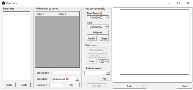
From the dropdown menu in Series tools you can set several types of TH functions, such as:
Eurocode 8 Spectrum: returns the design acceleration spectrum as defined in Eurocode 8 – EN 1998-1-1
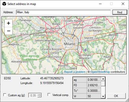
NTC2008 Spectrum: returns the design acceleration spectrum as defined in NTC2008 (Italian code of practice D.M. 14-01-2008). The program uses an automatic geo-referencing algorithm that allows to search for postal addresses finding the desired site.
NTC2008 Wind Load: gives the wind action as per NTC2008 (Italian code of practice D.M. 14-01-2008) as a function of building height
NTC2008 Snow Load: gives the snow load as per NTC2008 (Italian code of practice D.M. 14-01-2008) as a function of height of the building site
Linear TH: returns a linear loading ramp
Sinusoidal TH: returns a sinusoidal function on the base of the properties chosen by the user
Calculated Spectrum: this option is enabled only if user has requested the acceleration spectrum of the displayed acceleration TH through the button View spectrum
From File: allows the user to load a 2-columns text file containing a data series
Constant load: defines a constant loading plateau
EC8 Seismic Forces: allows to define a set of static lateral forces for each rigid diaphragm defined as per EC8/NTC2008, to be used in an equivalent static analysis;
EC1 Wind Load: wind load as per Eurocode 1
EC1 Snow Load: snow load as per Eurocode 1
EC1 Standard Fire Curve: fire curve as per Eurocode 1. The resulting series has time in seconds.
EC1 External Fire Curve: external fire curve as per Eurocode 1. The resulting series has time in seconds.
EC1 Hydrocarbon Fire Curve: hydrocarbon fire curve as per Eurocode 1. The resulting series has time in seconds.
![]() Set units: Custom user units can be defined by clicking on the opposite drop-down menu and choosing between:
Set units: Custom user units can be defined by clicking on the opposite drop-down menu and choosing between:
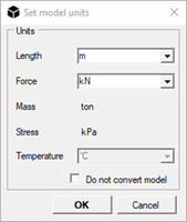
- Length:
o Metres [m] (default option);
o Centimetres [cm];
o Millimetres [mm];
o Kilometres [km];
o Inches [in];
o Feet [ft]
- Force:
o Newton [N];
o DecaNewton [daN];
o KiloNewton [kN] (default option);
o KiloPounds-force [kipf]
- Temperature:
o Celsius degrees [°C] (default option);
o Kelvin degrees [°K].
The following units are computed automatically in a consistent way:
- Mass:
o Megagram [Mg];
o Kilogram [kg] (default option);
o Gram [g];
o Ton [t];
o Ounce [oz];
o Pound [lb].
- Stress:
o MegaPascal [MPa];
o KiloPascal [kPa];
o Pascal [Pa] (default option).
![]() Check element connectivity: Checks counter-clockwise connectivity for elements with more than two nodes.
Check element connectivity: Checks counter-clockwise connectivity for elements with more than two nodes.
![]() Check element overlap: Checks if there are some overlaid elements.
Check element overlap: Checks if there are some overlaid elements.
![]() Check for free nodes: Check whether every node is connected to an element.
Check for free nodes: Check whether every node is connected to an element.
![]() Check element properties: Checks if section and material have been assigned to each element.
Check element properties: Checks if section and material have been assigned to each element.
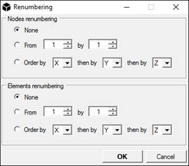
![]() Renumbering: Renumber the selected nodes and/or elements by the chosen criteria.
Renumbering: Renumber the selected nodes and/or elements by the chosen criteria.
![]() Check line mesh: Check all the line elements in the model to find out is there are disconnected beams (or trusses). This command corrects the mesh by dividing the lines that present apparent intersections (i.e. a node belonging to one element that lies on the joining line of the considered beam or truss).
Check line mesh: Check all the line elements in the model to find out is there are disconnected beams (or trusses). This command corrects the mesh by dividing the lines that present apparent intersections (i.e. a node belonging to one element that lies on the joining line of the considered beam or truss).
![]() Merge overlapped nodes: Merges the nodes with the same coordinates in the whole model.
Merge overlapped nodes: Merges the nodes with the same coordinates in the whole model.
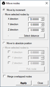
![]() Move nodes: By selecting Move by increment, it moves the selected nodes of the specified quantity. By selecting Move to absolute position, it moves the selected nodes in the chosen directions to the specified position.
Move nodes: By selecting Move by increment, it moves the selected nodes of the specified quantity. By selecting Move to absolute position, it moves the selected nodes in the chosen directions to the specified position.
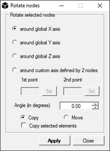
![]() Rotate nodes: Rotate the selected nodes with respect of a specified axis.
Rotate nodes: Rotate the selected nodes with respect of a specified axis.
To define a custom axis select two nodes in the model.
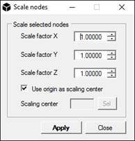
![]() Scale nodes: Scale the selected nodes (and elements) with respect to a specified point in the 3D space.
Scale nodes: Scale the selected nodes (and elements) with respect to a specified point in the 3D space.
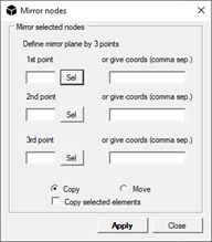
![]() Mirror nodes: Mirror the selected nodes (and elements) with respect to a specified plane in the 3D space defined by 3 points.
Mirror nodes: Mirror the selected nodes (and elements) with respect to a specified plane in the 3D space defined by 3 points.
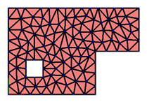
![]() Mesh area: Automatically meshes an area into triangular elements. Choose the maximum area of the triangles to be generated, select the nodes of the perimeter of the area to mesh and then click on the Acquire selection button under the Filled areas section. To insert a hole in the mesh, select the nodes of the hole and then press the Acquire selection button under the Holes section. To confirm press OK.
Mesh area: Automatically meshes an area into triangular elements. Choose the maximum area of the triangles to be generated, select the nodes of the perimeter of the area to mesh and then click on the Acquire selection button under the Filled areas section. To insert a hole in the mesh, select the nodes of the hole and then press the Acquire selection button under the Holes section. To confirm press OK.
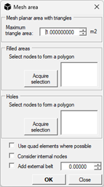
When the option “Consider internal nodes” is selected, only the groups of nodes forming filled polygons are considered, even if non-convex. The “Add external belt” option allows to mesh convex surfaces, extending them outwards for the desired length.
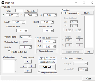
![]() Add wall: The command allows to insert and mesh walls of arbitrary dimensions, made of Quad elements.
Add wall: The command allows to insert and mesh walls of arbitrary dimensions, made of Quad elements.
To insert a wall insert the origin coordinates on the Origin box and specify its dimension on the Length and Height box.
Enabling the Add upper cut/sloping option it is possible to insert sloping walls by specifying the Wall type and the angle of inclination (with angle [°] box). Clicking on the Wall type drop down menu the following options are available:
- x;
- y;
- vertical that is in the working plane direction.
x and y can be used only if the working plane is set as XY, otherwise they have no effect.
Through the Drawing controls pan it is possible to move in the working plane to insert quickly adjacent panels.
Enabling the Add openings option, holes can be added in the wall.
![]() Automesh wall: The command allows to automatically mesh all the quad elements in the model, using the size specified in the Options under Size for IfcWall mesh.
Automesh wall: The command allows to automatically mesh all the quad elements in the model, using the size specified in the Options under Size for IfcWall mesh.
![]() Mesh tapered beams: The command allows to automatically mesh all line elements of a model having variable cross section, i.e., different initial and final sections.
Mesh tapered beams: The command allows to automatically mesh all line elements of a model having variable cross section, i.e., different initial and final sections.
![]() Expand macroelements: The command allows to automatically mesh all macro elements in a model, expanding them as specified by the submodels in the macro folder.
Expand macroelements: The command allows to automatically mesh all macro elements in a model, expanding them as specified by the submodels in the macro folder.
![]() Add belt: The command allows to mesh both concave and convex belt, for example, on an existing slab.
Add belt: The command allows to mesh both concave and convex belt, for example, on an existing slab.
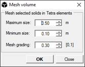
![]() Mesh volume: this command allows to mesh solids into tetrahedral elements. In Maximum size box the maximum characteristic size of the mesh element must be inserted; Minimum size sets the minimum characteristic size and Mesh grading sets the percentage variation of characteristic dimension amongst elements in target mesh. Press OK to mesh selected elements.
Mesh volume: this command allows to mesh solids into tetrahedral elements. In Maximum size box the maximum characteristic size of the mesh element must be inserted; Minimum size sets the minimum characteristic size and Mesh grading sets the percentage variation of characteristic dimension amongst elements in target mesh. Press OK to mesh selected elements.
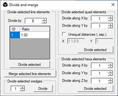
![]() Divide and merge: this command allows to divide in equal parts the selected line (2 nodes) and quad (4 nodes) elements. Moreover, it is possible to merge the selected line elements having the same first local axis. Divide commands are available also for Quad and Hexa elements.
Divide and merge: this command allows to divide in equal parts the selected line (2 nodes) and quad (4 nodes) elements. Moreover, it is possible to merge the selected line elements having the same first local axis. Divide commands are available also for Quad and Hexa elements.
Wall to frame: this command allows to obtain a frame from a shell wall model. This is particularly useful to convert into beams all the Wall elements imported from a Midas GEN® model or to apply plastic hinges to the beams obtained from walls. The local y axis of Quad element becomes the x axis of the beam.
Extrude section: this command extrudes the selected beam elements accordingly to their transversal section into shell or solid models. This is particularly useful to convert a part of a frame into a shell or solid model to allow detailing analyses, such as local buckling.
![]() Change element type: This command allows changing the type of the selected elements. Pick a transformation from the menu and then press OK.
Change element type: This command allows changing the type of the selected elements. Pick a transformation from the menu and then press OK.
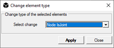
The possible conversions are:
- Truss->Beam: from truss to beam
- Beam->Truss: from beam to truss
- Beam->Beam3: from beam to 3 node beam (middle node)
- Beam3->Beam: from 3 node beam to beam
- Spring->Beam: from spring to 2 node beam
- Beam->Spring: from 2 node beam to spring
- Quad->Tria: from quad to tria
- Quad->Quad8: from quad to quad8
- (planar)->PlaneStress: from planar element to plane stress
- (planar)->Shell: from planar element to shell
- (planar)->PlaneStrain: from planar element to plane strain
- Tetra->Tetra10: from tetra to 10 nodes tetra
- Hexa->Hexa20: from hexa to 20 nodes hexa.
![]() WARNING: PlaneStress and PlaneStrain elements can be used only in XY plane.
WARNING: PlaneStress and PlaneStrain elements can be used only in XY plane.
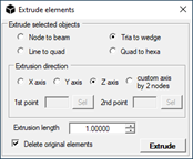
![]() Extrude elements: this command allows to extrude elements from selected nodes, tria or quad elements. In all cases, the Extrusion direction and the Extrusion length must be provided by the user.
Extrude elements: this command allows to extrude elements from selected nodes, tria or quad elements. In all cases, the Extrusion direction and the Extrusion length must be provided by the user.
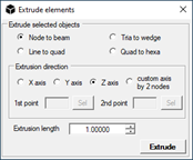
If Node to beam is checked, the selected nodes will be extruded to beam elements. Remember to assign a material and a section to the obtained beams.
If Tria to wedge is selected, the selected tria elements will be extruded to wedge elements. By checking Delete original elements, the initial tria elements will be deleted after extrusion. The material of newly created elements will be assigned equal to material of original tria elements.
If Quad to hexa is selected, the selected quad elements will be extruded to hexa elements. By checking Delete original elements, the initial quad elements will be deleted after extrusion. The material of newly created elements will be assigned equal to material of original quad elements.
![]() Cut: Cuts the selected elements (CTRL+X).
Cut: Cuts the selected elements (CTRL+X).
![]() Copy: Copies the selected elements (CTRL+C).
Copy: Copies the selected elements (CTRL+C).
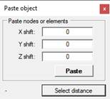
![]() Paste: To paste the copied/cut elements insert the shift coordinates in the opposite boxes and then click in Paste button (CTRL+V).
Paste: To paste the copied/cut elements insert the shift coordinates in the opposite boxes and then click in Paste button (CTRL+V).
![]() Undo: Undo the last action.
Undo: Undo the last action.
![]() Redo: Redo the previous action.
Redo: Redo the previous action.