Composite sections
The support for composite sections includes:
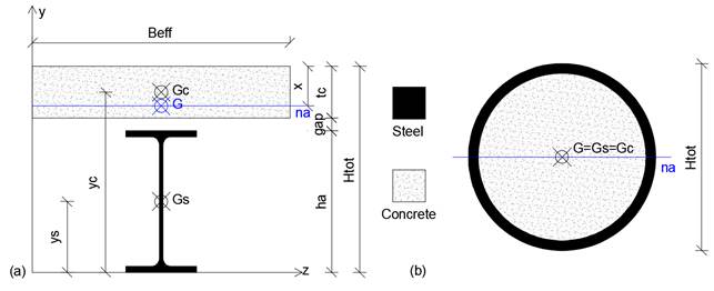
- Beams with slab like in figure (a) and
- Columns with coincident centres of gravity (b).
A composite section is automatically detected when:
- Two or more filled figures, one of them associated to a steel material and one to a concrete material;
- Properties of the composite section are defined inside the mask Section properties / Properties in order to distinguish a beam or a column section.
![]() WARNING: The effective width of the section Beff must be evaluate by the user as per current code of practice.
WARNING: The effective width of the section Beff must be evaluate by the user as per current code of practice.
The stiffness of beam elements having such sections is evaluated as follows. With subscript s, steel properties are described, while the ones related to concrete have the subscript c.
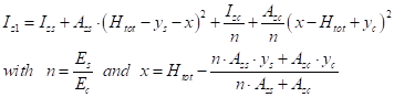
For beams, the moment of inertia for positive bending around the elastic neutral axis na is calculated as:
The moment of inertia of the section for negative bending around the plastic neutral axis is equal to the inertia given by the steel section, as the concrete part is considered as cracked.
As a whole, bending stiffness is estimated as per EC4 and as a function of the factors Mpos and Mneg which can be changed in the “Properties” input mask (figure a).
(a) 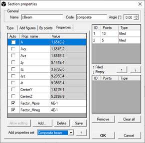 (b)
(b) 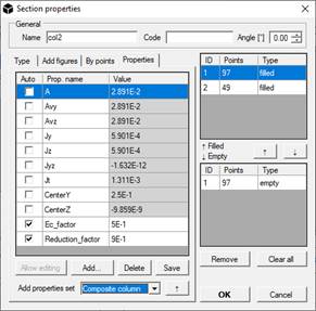
Hence, the resulting bending stiffness is:
![]()
The remaining properties for the beam section are all calculated by dividing the concrete contribution by n.
For composite columns, once the factors Ec and R have been specified in the “Properties” mask (figure b), the inertial properties of the section are calculated as follows:
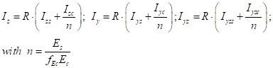
The remaining properties are all calculated by dividing the concrete contribution by n.