Tension-Only and Compression-Only elements: the topic of allowing and how to handle the superposition of effects in structural analysis is much debated. Many programs give the possibility to consider the nonlinear behavior of these elements (e.g., cable ties in steel str.). In this article we will see how these analyses work and how to set them up.
Modeling structural elements that work only in tension (ties, cables) or only in compression (struts) represents one of the most interesting challenges in finite element analysis. Indeed, these elements introduce nonlinear behaviors that, theoretically, should invalidate the principle of superposition of effects. However, many commercial software programs still allow the superposition of load combinations to be used even in the presence of such elements. How is this possible?
The Problem of Nonlinearity
Tension-only and compression-only elements exhibit inherently nonlinear behavior: their stiffness changes depending on the state of stress. A tie rod, for example, contributes to structural stiffness only when in tension, while it becomes virtually inactive when subjected to compression.
This change in stiffness as a function of applied load violates the superposition principle, which is based on the assumption of linearity of the structural system. Theoretically, therefore, it should not be possible to combine the results of different analyses containing such elements.
The Solution: Iterative Linearization
The key to solving this apparent paradox lies in the iterative linearization process that many software programs implement "behind the scenes." The process works as follows:
1. Iterative Analysis for Each Load Case.
Each elementary load case is analyzed separately through an iterative process:
- Initialization: It starts by assuming all active elements
- Linear resolution: One solves the system with the current configuration
- Checking states: For each element, it is checked whether the stress is consistent with the expected behavior
- Update: Elements in inconsistent states are deactivated or reactivated
- Convergence: The process is repeated until equilibrium is reached
2. Freezing the Configuration.
Once the iterative analysis converges, the structural configuration (active/inactive elements) is "frozen" for the specific load case. At this point, the behavior is effectively linear.
3. Standard Superposition.
The results of the individual load cases, now linearized, can be superposed normally according to the coefficients of the combinations provided by the standards.
Equivalence with Nonlinear Analysis
This approach is mathematically equivalent to performing a nonlinear analysis with a single load increment for each elementary case. The main difference is that the software masks this complexity by presenting it as a linear analysis with special elements.
Validity and Limitations of the Approach
The effectiveness of this method depends strongly on the type of structure and configuration of nonlinear elements:
Favorable Cases
- Cross-arranged cable bracings: They represent the ideal case for this approach. Regardless of the direction of loading, the stiffness of the bracing system remains essentially constant because always one of the two diagonals is active. In this case, the superposition of effects produces very accurate results.
- Structures with few nonlinear elements: When tension-only or compression-only elements represent a small percentage of the total stiffness, the error introduced by superposition is generally negligible.
- Elastic soil: Winkler-like springs used for elastic soil set as compression-only follow the same concepts. Limited portions of the slab or foundation are subject to tension, so iterative linearization is applicable.
Problematic Cases
Structures with many cables: When numerous elements change state frequently between different loading conditions, the approximation may become less reliable.
Combinations with Response Spectrum: This represents the most critical case. The response spectrum calculation is based on the modal characteristics of the structure (frequencies and modal shapes), which depend on the stiffness matrix. If the elements change state, the modal characteristics also change, making the superposition theoretically inconsistent.
As an example, Winkler-like springs for soil register tension only in response-spectrum cases.
In the case of seismic analysis with elements with unidirectional behavior, the designer must pay special attention:
- Response Spectrum: Overlap can lead to significant errors, especially when evaluating displacements
- Conservative Configuration: It is often preferable to assume all active bracing during seismic analysis
- Verification with Time-History: For critical structures, it is advisable to perform verifications with nonlinear time-history analysis.
For proper use of this approach, it is suggested that:
1. Check for consistency: Check that the main elements maintain similar states across load cases
2. Check analysis: Perform at least one complete nonlinear analysis for the most critical combinations
3. Document assumptions: Record choices made for future verification
4. Evaluate on a case-by-case basis: Do not automatically use the approach without evaluating its appropriateness
Practical case
Let us assume as an example the following
single-story industrial building with bracing cables arranged in a cross for
the longitudinal direction. We also adopt a compression-responsive soil only.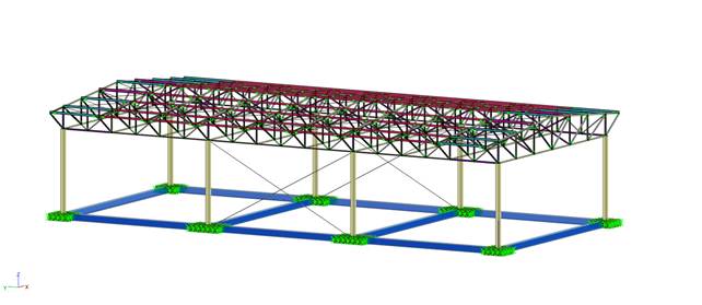
After drafting a linear model, these steps were necessary to perform the calculation of tension-only bracing and compression-only elastic soil:
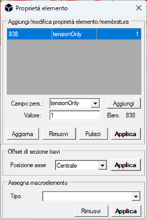
- Applying the tensionOnly = 1 flag to the bracings: this will affect both the analyses and the verifications. In the latter, only the results of axial verifications will be shown;
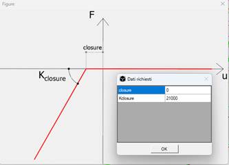
- Setting soil springs: simply assign a Gap spring to the soil, canceling the closure value and setting the same linear compression stiffness.
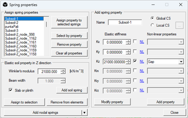
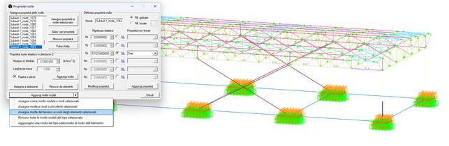
At this point it is necessary to remove the elastic soil property from the elements with the "Remove from elements" command and reassign equivalent springs to the elastic soil with the "Assign soil springs to selected element nodes" command. In this way it is possible to consider the same effects in the soil but at the nodal level, with springs inheriting the initial "compression-only" setting.
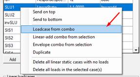
- Setting up the analyses, converting linear static cases to nonlinear. Modal and response-spectrum analyses remain, as mentioned, linear and will therefore provide any compressions in bracings or tractions in the soil. In the case of seismic analysis with response spectrum, cases that accommodate accidental eccentricities can also be converted to nonlinear.
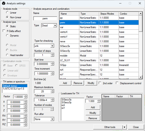
- Perform the analysis. The results present for each nonlinear load case and for each combination involving them 2 times, identified with 0 and 1.
State 0 (meaning that the load multiplier is zero) should not be considered either by the user to check the results or during verification.
As mentioned, the iterative analysis checks the goodness of balance, so it may not be possible to reach equilibrium all the time. From the analysis log we see that all analyses were successfully completed. If this is not the case for some load cases (e.g., those with wind loads) it is possible to raise the tolerance in Analysis Settings.
We then check that the bracing has not regained compression by consulting the envelope.
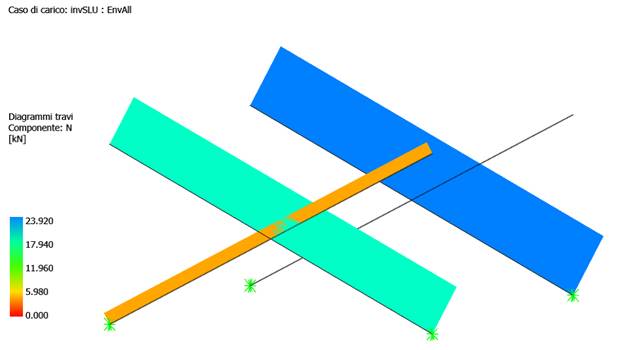
In fact we find only traction in the bracing.
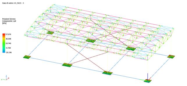
As for the terrain, let us now see the results Terrain pressures from the menu in status bar, after applying compression-only (Gap).
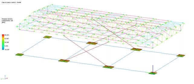
Results with compression-only elastic soil in envelope static combinations
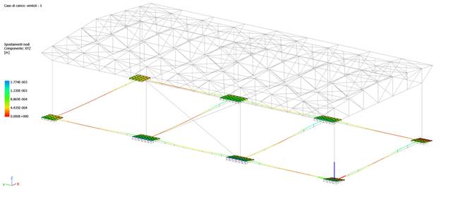
As can be seen from the results, the model still has pulls, mainly due to the wind load case, of which we can appreciate the deformation and visualize the uplift of the plinths (structure subjected to wind only, with no other vertical loads or own weight).
Let us now check the stresses in the soil
springs. Since these are zero-length springs, their local axes are the global
axes, so we read soil tension or compression at "Beam diagrams,"
component Vz.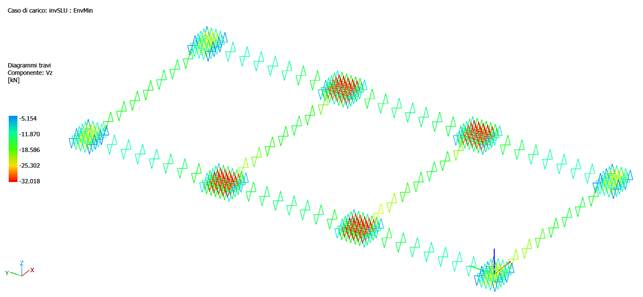
All springs are compressed in EnvMin, while EnvMax records only zeros (no traction). We then find that the traction shown in the soil pressures is due to the rigid rotation of the plinth by the horizontal wind load, which drags the extreme nodes of the plinth upward. The soil pressure is calculated by the program as vertical displacement times the Winkler modulus, so to the designer the necessary conclusions.
Conclusions
The use of superposition of effects with tension-only and compression-only elements represents an engineering compromise between theoretical rigor and computational efficiency. When applied correctly and in appropriate cases, it provides sufficiently accurate results for most practical applications.
However, it is critical that the designer understands the underlying mechanisms and limitations of the approach so that he or she can critically evaluate when it is appropriate to use it and when full nonlinear analysis is required. The key to success lies in balancing pragmatism and scientific rigor, always keeping structural safety as the primary goal.
NextFEM Designer does not present the user with a pre-coded procedure for setting up and performing this type of analysis, preferring that the user always be aware of the limitations and opportunities of this analysis. We have seen that:
- In the case of bracings reacting only in tension (and therefore considered "in call" in compression), the analysis provides the result due, taking care to also skip typical beam verifications (e.g., buckling) but provide only the axial one
- In the case of soil in compression, it is necessary to use springs equivalent to elastic soil, placed automatically by the program. The soil response is contained in the results of the springs, which result all compressed. The contour of the Soil Pressures as we have seen can present some surprises, being calculated as the vertical displacement of the shell node (which is at the head of the soil spring) by Winkler's modulus. Correctly in fact, the shell can rotate rigidly under the effect of horizontal loads (e.g., wind).
In the case of the soil, the effective tension recorded by the pressures on the plinth soil is due to the fact that:
- we superimpose effects on the plinth from different stiffness matrices: for vertical loads, all the soil springs are compressed, whereas for wind load cases this does not happen
- the soil springs are no longer "few" compared to the number of total elements in the model, as required by the exhibited method.
In this case, it is appropriate to transform the SLU combinations to a nonlinear load case and perform a comparison analysis to estimate the error on the results obtained. Obviously, this operation is possible only for SLU combinations; the seismic ones contain response spectrum cases and it is not possible to perform this command.
The analysis confirms previous results, which underestimated traction by a small amount.