The overturning checks are outside the finite element calculation, being a rotation equilibrium of the entire model considered as a rigid body. In this article we will see how these checks are carried out for structures and how it is possible to automate them with NextFEM Designer.
The overturning checks , mandatory for all types of construction, are always onerous since they must be carried out manually. In fact, the infinite element method is of no help, since it has been designed to provide the deformations of the calculated structure, and cannot consider the construction as a rigid body, except through dedicated approaches.
Overturning is a kinematic analysis , aimed at ascertaining the static balance of the artefact, which consists in verifying that the overturning moments are less than the stabilizing ones. The analysis is usually carried out by hypothesizing a point (structures in 2D) or an axis (in 3D) of rotation which acts as a pole for the calculation of the moments of each individual load acting on the structure, including its own weight.
This type of analysis is therefore used to test the overall stability of the product under the design actions in ultimate conditions (SLU) , and is regulated by the application of combination coefficients that can vary from norm to norm. In the NTC2018 §2.6.1 , the coefficients for the equilibrium combinations as rigid body EQU vary according to the type of load:
- For G1 permanents (own weight): 0.9 if favorable, 1.1 if unfavorable
- For non-structural G2 permanents (carried): 0.8 if favorable, if 1.5 if unfavorable
- For Q variables: 0 if favorable, 1.5 if unfavorable.
For scaffolding and stages for example, the EN 12811-1 standard explicitly refers to EN 12812 Support structures for permanent works - Performance requirements and general design , which reports the following coefficients:
- Permanent loads Q1 (own weight): 0.9 if favorable, 1.35 if unfavorable
- Persistent variable loads Q2 (e.g. supported construction): 0.9 if favorable, 1.35 if unfavorable
- All other loads: 0 if favorable, 1.5 if unfavorable.
Note that the safety margin against tipping is always 1.5, even in the case of only self-weight and weight bearing (1.35 / 0.9 = 1.5).
We now come to the calculation example. Let's consider an audio tower built with scaffolding sets as a case study. This is the typical temporary construction which requires an appropriate overturning check, for example against the wind. The audio tower has dimensions 2.5 x 2.5 x 9 . 5 m
The calculation, if carried out manually, must consider the worst situation, that is, less conservative, between the 2 axes , orthogonal to each other, passing through each node tied to the base. In other words, we consider all the possible tilting axes of the structure, 1 per side.
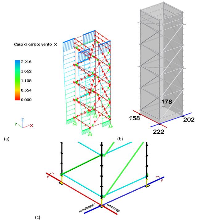
Wind load in X for an audio tower (a), numbering of the base nodes (b) and calculation axes for overturning with respect to a node (c)
For simplicity of exposure, we assume the horizontal forces shown in the following figure:
- The horizontal load ( a) in the case of load var (variables) , is 1kN / m for a result equal to 2.5kN;
- The vertical load (b) in the case of perm (permanent) load , which represents the weight of a ballast anchored to the base current, and is 6.4kN / m for a result equal to 16kN.
Self-weight is not considered.
To determine the weight of the ballast we must apply the safety coefficients to the overturning and stabilizing moments calculated for the perm and var load cases :
- For the load case var : Mribaltante = 2.5kN * 9.44m = 23.61 kN * m
- For the perm load case : Stabilizer = x * 2.5m
By imposing 1.5 * Mribaltante = 0.9 * Stabilizer , we find the weight of the ballast x , equal to 1600kgf. If we imagine the ballast astride the current, these translate to 6.4kN / m as in the following figure (b).
(a)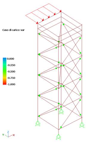 (b)
(b)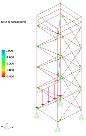
Variable load stabilizer (a) and ballast weight modeling (b)
To test the capabilities of the verification algorithm integrated in NextFEM Designer, we create from Assign / Analysis Settings… a combination of our load including var and perm . The combination factor is not influential, during the rollover calculation the specified factors will be replaced by the partial safety factors seen previously.
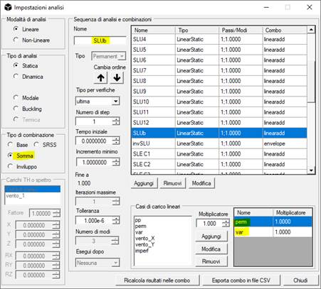
Now let's launch the command Results / Advanced data / Verify overturning . The following mask will appear:
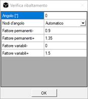
The user is asked for the angle in degrees on which to set the axes. This angle measures the deviation of the sides of the building with respect to the global X and Y axes. case is null.
The safety factors listed above for EN 12811-1 are also preset.
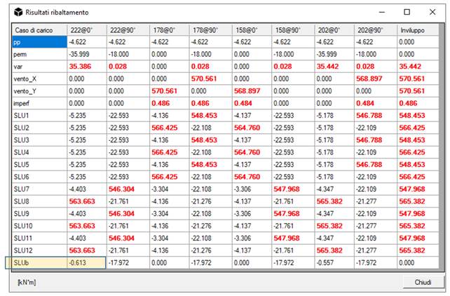
The command returns the stabilizing (- sign) and overturning (+ sign) moments added, in the unit of measurement of the model, already inclusive of the specified coefficients.
Therefore, a negative moment means that the overturning verification is satisfied, a negative one that the structure overturns.
The verification is carried out for all the axes passing through each base node, at 0 ° (parallel to global axis X) and at + 90 °.
As you can see in the cell highlighted in the following table, the system does not tip over in the SLUb combination calculated manually previously.
The algorithm implemented in NextFEM Designer for overturning does not require the finite element calculation, treating the whole model as a rigid body and without considering constraints and their possible reactions.
The procedure described therefore saves a lot of precious time, automating the calculation of the overall stability of the structure, in particular for scaffolding or stages in which this type of verification is mandatory.