Custom checking and output
If your preferred design code is not built-in into NextFEM Designer or you need to use your own relationships for checking, you can use NextFEM scripting engine.
The syntax is very simple and straightforward, you can even copy your formulas from a spreadsheet since the most common math functions are supported.
The script must be loaded in the Verification window (Results/Verifications… command); to do so, create a text file and place it into the subfolder “verification” in the program installation directory (typically it’s C:\Program Files\NextFEM\NextFEM Designer\verification).
The file must have the extension .nvv to be read automatically and to appear in the drop-down list as below.
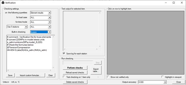
You can also edit your script in the text area of Verification window, or you can modify the file outside the program.
Writing checks
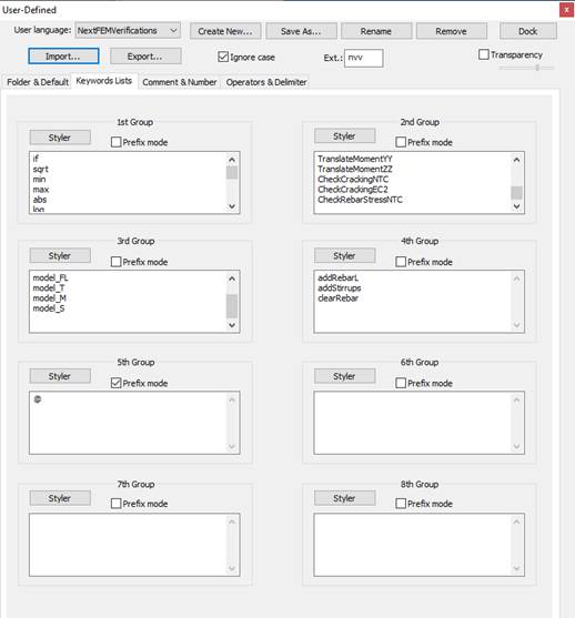
We recommend an editor with syntax highlight for writing your script, such as Notepad++ (https://notepad-plus-plus.org/).
A setting for the syntax highlight for Notepad++ can be found in the “verification” folder (NextFEMVerifications.xml). From inside Notepad++, it can be loaded with the command Language/Define your language… and by clicking on Import… . Then, you’ll find the entry “NextFEMVerifications” in the top dropdown menu. Also, in the tab Keyword Lists, you can see all the supported commands for scripting that will be highlighted during editing.
Open the sample script called “trusses.nvv” supplied with the program, in the “verification” folder.
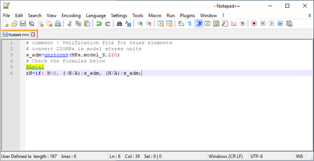
The few lines contained are self-explanatory. Note the keyword “unitconv” to convert units (“model_S” is the current stress units in the model), the @ character to create a column as output and the if(condition, true, false) structure.
In this tutorial, we’ll gradually see how to develop a more complex script that can suit your needs.
Using blocks
The checking engine supports the code execution in blocks. Each block is delimited by the identifiers as in the following example and must be named with a floating point number (for example, 0.6).
$$0.6
# this is a comment – we are inside the block named 0.6
# the block named 1.0 will be executed only if the variable SecType is equal to 1 (==)
execif(SecType==1,1.0)
$!
To call each block for execution, the following keywords are available:
- exec(0.6) : executes the code block named 0.6
- execif(condition, 0.6): executes the code block named 0.6 is condition is true.
Customizing output
Output coming from your checking is organized in columns containing numbers or Boolean values (true or false). To declare a column, use the character @ before the column name, the write the output quantity in the following line. For example:
@MomentCheck
MEd/MRd
This will create a columns named “MomentCheck” and will insert the value resulting from the expression MEd/MRd in the row corresponding to the node or the element to be checked.
Script example
Variables don’t need to be declared; simply initialize them with a value or an expression. For example:
# design yield strength 391.3 MPa
fyd=391.3
# 500 mm section height
h=450
# 50 mm concrete cover
c=50
# 628 mm2 lower bars - 2phi20
AsInf=400
# 308 mm2 upper bars - 2phi14
AsSup=280
# 20x10^6 Nmm = 20.0 kNm Design Moment
MEd=2.0E7
By default, all variables are double, but you can always use them as a lower type:
# variable used as a boolean: 1 is true, 0 is false
positiveMoment=if(MEd>=0,1,0)
Let’s see in action a simple script to estimate the rebar area needed in a
concrete beam. Blocks can be inserted freely at any line of the code.
# design yield strength 391.3 MPa
fyd=391.3
# 500 mm section height
h=450
# 50 mm concrete cover
c=50
# 628 mm2 lower bars - 2phi20
AsInf=400
# 308 mm2 upper bars - 2phi14
AsSup=280
# 20x10^6 Nmm = 20.0 kNm Design Moment
MEd=2.0E7
# variable used as a boolean: 1 is true, 0 is false
positiveMoment=if(MEd>=0,1,0)
# call the function 5.0
exec(5.0)
# conditional function call: positiveMoment is true so 2.0 will be called
execif(not(positiveMoment),1.0)
execif(positiveMoment,2.0)
# Negative Resistant Moment estimate
$$1.0
MRd=-0.9*d*fyd*AsSup
minArea=MEd/(-0.9*d*fyd)
$!
# Positive Resistant Moment estimate
$$2.0
MRd=0.9*d*fyd*AsInf
minArea=MEd/(0.9*d*fyd)
$!
# calculate effective section height
$$5.0
d=h-c
$!
@MomentCheck
MEd/MRd
@_MinimumNeededArea
minArea
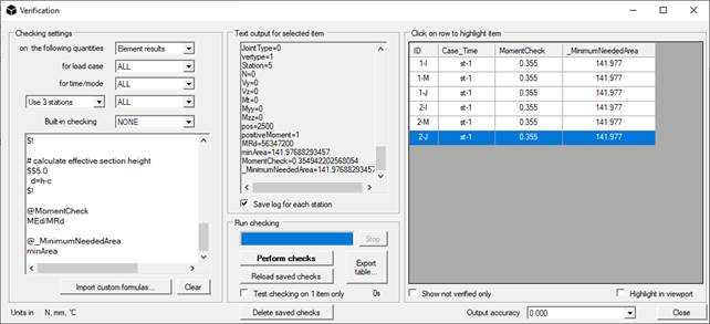
To start, you must have results in our model, otherwise the checking will not be executed.
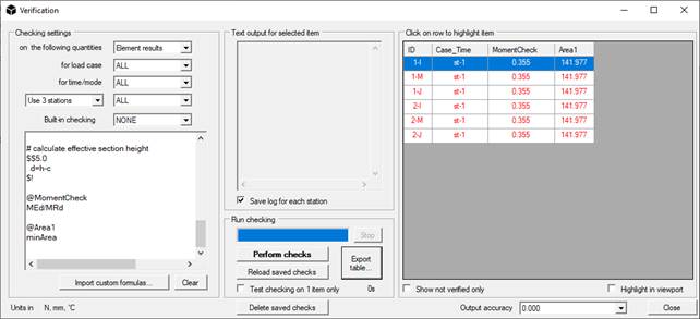
First of all, copy the sample script in the text box. Then choose the set of data you need in the first dropdown menu (Element results), and the number of stations (Use 3 stations). To see all the values for the elements given by default, please check the scripting reference in Chapter 4 of the users’ manual.
Finally press Perform check, the table on the left will be populated with 3 rows for each element.
Columns highlight
If a column contains a values that is greater than 1, the entire row will be automatically highlighted in red.
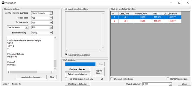
Try to append the following code to the previous script:
@Area1
minArea
If you press the button “Reload saved checks”, the program will compact the rows by using the maximum for each element.
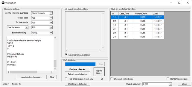
To avoid highlighting in a certain column, declare it with “@_”. For example:
@_Area1
minArea
Dimensioning concrete members
Using some special commands, it’s possible to dimension concrete members by adding longitudinal and shear reinforcements on the base of custom relationships.
In the following, you can find a sample to dimension concrete beams by calculating the needed shear area under pure flexural behaviour.
# dimensioning of rebar in a beam part of a rigid diaphragm – clear all rebar in current element
clearRebar
# long. rebar strength fydl
fydl=unitconv(MPa,model_S,391.3)
# stirrup strength
fyds=fydl
# design moment - take maximum and minimum over beam
Mpos=MmaxZ
Mneg=MminZ
# set rebar cover to 40mm
c=unitconv(mm,model_L,40)
# calculate effective section height
d=h-c
# estimate rebar area for design moments
AsTop=max(abs(Mpos)/(0.9*d*fydl),0.0013*b*d)
AsBot=max(abs(Mneg)/(0.9*d*fydl),0.0013*b*d)
# insert rebar in the model - find bar diameter for 3 bars at bottom and 3 at top
nBars=3
TopD=getBarDiam(AsTop/nBars)
BotD=getBarDiam(AsBot/nBars)
TopArea=pi*TopD^2/4
TopArea=unitconv(mm^2,model_L^2,TopArea)
BotArea=pi*BotD^2/4
BotArea=unitconv(mm^2,model_L^2,BotArea)
# stirrups D=8mm
stirrArea=unitconv(mm^2,model_L^2,50)
stirrSpac=unitconv(mm,model_L,150)
# cycle for bars
i=1
xdim=(b-2*c)/(nBars-1)
execwhile(i<=nBars,1.0)
$$1.0
# design material ID for bars = 2
# X coord., Y coord., bar area, design material ID, Linit [0,1), Lend (0,1]
# top
addRebarL(-b/2+c+xdim*(i-1),h/2-c,TopArea,2,0,1)
# bottom
addRebarL(-b/2+c+xdim*(i-1),-h/2+c,BotArea,2,0,1)
# shear reinforcements
# legs in Y, legs in Z, bar area, spacing, design material ID = 2, Linit [0,1), Lend (0,1]
addStirrups(2, 2, stirrArea, stirrSpac, 2, 0,1)
i=i+1
$!
The code above estimates the needed rebar area to resist the bending moment around the major section axis. The instructions to add rebar to beams are:
o
addRebar: adds
longitudinal rebar to the current element.
Usage: addRebar(zCoord, yCoord, rebarArea, design material ID, startAt [0,1),
endAt (0,1] ).
Example: addRebarL(-b/2+40,-h/2+40,201.0,2,0,1)
adds a rebar of area 201.0 at position 40, 40 from the bottom left corner of
the section, for the whole element.
From version 1.8.3, the position of the rebar must be given with respect to
the center of the section.
o
addStirrups: adds
stirrups to the current element.
Usage: addStirrups(legs in Y, legs in Z, single bar area, spacing, design
material ID, startAt [0,1), endAt (0,1] ).
Example: addStirrups(2, 2, 50.0, 200, 2, 0,1)
adds 2-by-2 legs stirrups, each one of area 50.0, at 200 of spacing, for the
whole element.
o clearRebar: clear all rebar, including stirrups, in the current element.
o getBarDiam: gets the minimum diameter of a longitudinal bar required to satisfy the given area. The output is in mm. Example: getBarDiam(2.01) # for a model in cm, returns 16.
o getStirrupDiam: gets the minimum diameter of a stirrup bar required to satisfy the given area. The output is in mm. Example: getStirrupDiam(0.5) # for a model in cm, returns 8.
TranslateMomentYY and TranslateMomentZZ
As required by the codes (EC2 6.2.2 (5) and 6.2.3 (7)), due to the fragile behavior of the concrete and the formation of diagonal cracks, it is necessary to carry out the resistance verification of a section using an increased value of the tensile force on stretched bars.
In the practice of a structural verification procedure, this is equivalent to carrying out a translation of the envelope diagram of the bending moment, choosing the most penalizing combination of stresses. This translation distance is a function of the inclination of the concrete struts and the useful height of the section.
To get the translated value of the solicitation moment to be used in a verification script for NextFEM Designer, you can use the TranslateMomentYY and TranslateMomentZZ functions:
# Produces the variables Mzzmax, Mzzmin
TranslateMomentZZ (deltaZZ, position)
# Produces the Myymax, Myymin variables
TranslateMomentYY (deltaYY, position)
The required input parameters are:
- deltaZZ: the translation distance along the axis line for the moment around Z
- deltaYY: the distance of translation along the axis line for the moment around Y
- position: the position at which the values of the moment translated diagram are to be obtained. Measured from Node I along the axis line
The two functions respectively create the variables Mzzmax, Mzzmin, Myymax and Myymin which contain the maximum and minimum values, for the given position, of the moment diagrams.
If the element under test is part of a member consisting of more than a single element, the TranslateMomentYY and TranslateMomentZZ functions carry out the calculation using the bending moment diagrams of the contiguous elements if position + delta and position - delta fell outside the current element.
Finally, to dimension RC beams and walls you can use the following script, that uses block to distinguish which code to execute on the base of the current element.
# dimensioning of rebar in a beam part of a rigid diaphragm
clearRebar
# long. rebar strength fydl
fydl=unitconv(MPa,model_S,391.3)
# stirrup strength
fyds=fydl
# translate moment for current position (null translation) - major axis
#TranslateMomentZZ(0,pos)
# if beam go to block 1, if wall go to block 2
execif(isWall==0,1.0)
execif(isWall==1,2.0)
$$1.0
# design moment - take maximum and minimum over beam
Mpos=MmaxZ
Mneg=MminZ
# set rebar cover to 40mm
c=unitconv(mm,model_L,40)
# calculate effective section height
d=h-c
# estimate rebar area for design moments
AsTop=max(abs(Mpos)/(0.9*d*fydl),0.0013*b*d)
AsBot=max(abs(Mneg)/(0.9*d*fydl),0.0013*b*d)
# insert rebar in the model - find bar diameter for 3 bars at bottom and 3 at top
nBars=3
TopD=getBarDiam(AsTop/nBars)
BotD=getBarDiam(AsBot/nBars)
TopArea=pi*TopD^2/4
TopArea=unitconv(mm^2,model_L^2,TopArea)
BotArea=pi*BotD^2/4
BotArea=unitconv(mm^2,model_L^2,BotArea)
# stirrups D=8mm
stirrArea=unitconv(mm^2,model_L^2,50)
stirrSpac=unitconv(mm,model_L,150)
# cycle for bars
i=1
xdim=(b-2*c)/(nBars-1)
execwhile(i<=nBars,1.1)
$!
$$1.1
# design material ID for bars = 2
# X coord., Y coord., bar area, design material ID, Linit [0,1), Lend (0,1]
# top
addRebarL(-b/2+c+xdim*(i-1),h/2-c,TopArea,2,0,1)
# bottom
addRebarL(-b/2+c+xdim*(i-1),-h/2+c,BotArea,2,0,1)
# shear reinforcements
# legs in Y, legs in Z, bar area, spacing, design material ID = 2, Linit [0,1), Lend (0,1]
addStirrups(2, 2, stirrArea, stirrSpac, 2, 0,1)
i=i+1
$!
# wall
$$2.0
# design moment - take maximum and minimum over beam
Mpos=MmaxZ
Mneg=MminZ
# set rebar cover to 40mm
c=unitconv(mm,model_L,40)
# calculate effective section height
d=h-c
# estimate rebar area for design moments
As=max(max(abs(Mpos),abs(Mneg))/(0.9*d*fydl),0.003*A)
# insert rebar in the model - lattice reinforcement 20x20cm D=8mm
lt=unitconv(cm,model_L,20)
nBars=ceil((h-2*c)/lt)+1
# rebar diameter in mm
bd=8
RebArea=pi*bd^2/4
RebArea=unitconv(mm^2,model_L^2,RebArea)
# stirrups D=8mm
stirrArea=RebArea
stirrSpac=lt
# cycle for bars
i=1
xdim=lt
execwhile(i<=nBars,2.1)
$!
$$2.1
# design material ID for bars = 2
# X coord., Y coord., bar area, design material ID, Linit [0,1), Lend (0,1]
rpos=if(c+xdim*(i-1)>h,h/2-c,-h/2+c+xdim*(i-1))
# left
addRebarL(-b/2+c,rpos,RebArea,2,0,1)
# right
addRebarL(b/2-c,rpos,RebArea,2,0,1)
# shear reinforcements
# legs in Y, legs in Z, bar area, spacing, design material ID = 2, Linit [0,1), Lend (0,1]
addStirrups(2, 2, stirrArea, stirrSpac, 2, 0,1)
i=i+1
$!