NextFEM Designer allows implicit dynamic analyses to be carried out with impulse loads, provided the General Design module license is active. In this article, we will look at some recommendations for setting up the load and the analysis in the case of a blast load analysis.
Blast load analysis (or blasting analysis) is a dynamic analysis that describes the response of a structure subjected to the shock wave of an explosion and the pressure changes in the moments immediately following. It is necessary for structures that must be tested for shocks and/or explosions, and is covered in depth by the American AISC standard. The pressure on the building can be represented by a time-history series that describes the first "silence" part ( arrival time), the second with the impulse (shock wave), and finally, optionally, by a depression due to the movement of air masses.
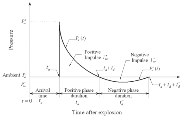
Graph from AISC Steel Design Guide 26, 2013
NextFEM Designer, since version 2.4, supports this type of analysis both for the built -in solver and in OpenSees.
In this article we will use a model of a steel building created by the Hi-Tech Project studio ( www.hitechproject.it )
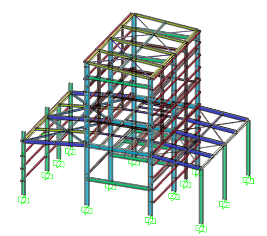
Setting the load multiplier functions
You can set the numerical series that, depending on the analysis time, will provide the load multiplier. The series must be of the User type .
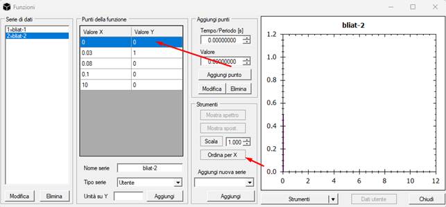
The new "Sort by X" command allows you to modify existing series by inserting previous or subsequent points. Click Edit (bottom left) to save the change.
NOTE: Do not apply the load at time 0, but leave at least one point at zero before the blast so as to have zero initial conditions for the dynamic analysis.
Dynamic Analysis Settings
The dynamic analysis must be performed considering appropriate damping, which should generally be calculated based on the period of the first vibration mode (or the fundamental mode for the load direction). It is important to define this value because it governs the building's response to free oscillations after an impulsive load.
It is recommended to always and only adopt mass-dependent damping ( Rayleigh damping). The critical damping constant at period T1 can be estimated as follows:

With  critical damping
ratio for the structure under consideration (e.g. for reinforced concrete
buildings it is typically assumed to be 5% and for steel buildings 2%).
critical damping
ratio for the structure under consideration (e.g. for reinforced concrete
buildings it is typically assumed to be 5% and for steel buildings 2%).
Eg.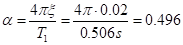
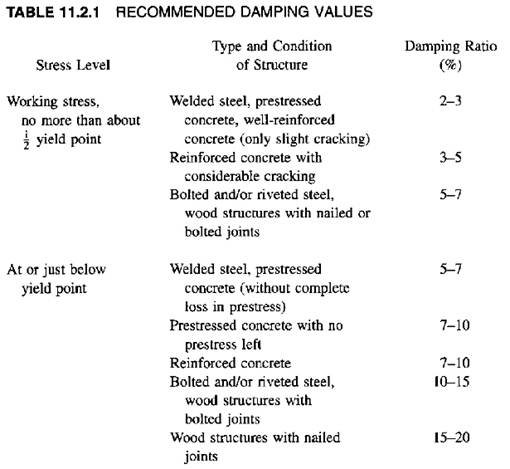
The image is taken from the text “ Dynamics Of Structures ” by Anil K. Chopra
To set up the analysis:
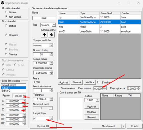
- In the “TH Series or Spectrum” box, select the appropriate time history for the main load (e.g., blasting for the building front). Set the General Factor (e.g., 1) and leave the directional factors null .
-
It is advisable (but not mandatory for numerical
purposes) that the analysis be performed after the permanent loads have been
applied to the building, therefore it is necessary to select an analysis from
those available in the "Run after" drop-down menu.
NOTE: When the OOFEM solver is selected, the analysis preceding a dynamic
analysis must also be dynamic. In the example, the "pp" case is a
dynamic analysis with  (very high)
results
(very high)
results
. The results include the first loading phase.
NOTE1: When the OpenSees solver is selected in the general options, the
preceding analysis can also be static. The results start from the end of the
first loading phase.
-
IMPORTANT : the
analysis step must be such as to have an analysis instant exactly at the time
corresponding to the peak of the TH function.
New TH Options Mask
The mask allows you to set which loads to associate with another TH function instead of the one already set at a general level for the dynamic analysis.
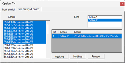
To add a function, select the loads involved and the associated function, then the Add button .
blast pressures is analyzed as in the following figure.
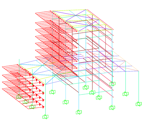
Blast pressures
Performing the analysis for a steel building, we obtain a response in terms of displacement at the top in the free oscillation phase.
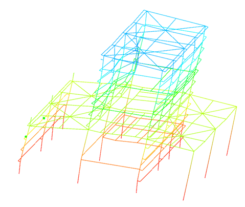
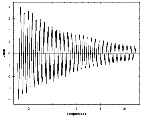
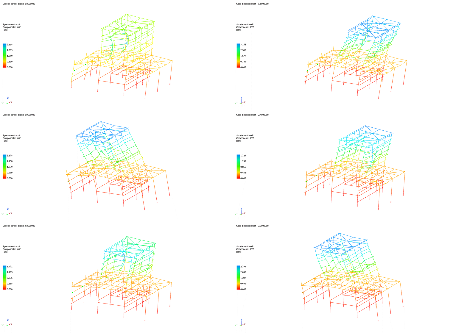
The deformation obtained in free oscillations is visible in the following animation.
Note for results obtained from OpenSees
The beam results available from OpenSees are limited to the element's extreme cross-sections. NextFEM Designer allows you to reconstruct the internal points (knowing the loads) using the spring line equation (for both Euler-Bernoulli and Timoshenko beams).
It is recommended that, before carrying out checks on the beams, you set an odd number of stations in Options / Solvers mask / “Mesh and output options” box.

Then press Results / More output stations.
An odd number is required to have a station in the middle of the beams.