In this article we will see how to model CLT (Cross Laminated Timber) structures within NextFEM Designer, with the aim of providing the necessary knowledge for the calculating engineer of these structures
Cross-laminated panel structures (or CLT, or X-Lam in Southern Europe) are increasingly widespread thanks to their practicality and speed of execution on site, as well as ensuring good performance even in seismic areas.
In CLT wall assemblies, energy dissipation is entrusted solely to the metal connections, which generally exhibit sufficient ductility to be able to operate with behavior factors > 1.5. The main connections used are:
- hold-down and tie-down , positioned at the corners of the walls, to control the lifting (rocking) of the panel;
- angle brackets (or corner-brackets), generally positioned in the center of the lower/upper side of the wall, to counteract sliding (shear) at the base and top;
- screws, used to connect the vertical walls along their common edges, or to connect the horizontal floor panels.
Regardless of the chosen behavior factor, which also varies depending on the h/b shape ratio of the individual walls, the wooden panels therefore remain in the elastic range, allowing simplified modeling even for advanced analyses.
The modeling for a project with the usual Limit States (e.g. ULS and SLS) therefore consists in modeling the walls with flat elements (shells) and the connections using elastic springs. We will therefore check the walls in terms of elasticity, and the connections in terms of limiting capacity.
NextFEM Designer provides, already in the free basic version, mesh control and modeling tools suitable for this type of structures. We will see below how to produce a structure model in CLT in a few simple steps.
Wood material
From the Edit / Materials form, if you select the “Timber EN” library, the “Add CLT properties from selected” command appears, which allows the creation of an isotropic and elastic material with mechanical characteristics equivalent to the set of boards with fibers oriented at 0° and 90° that compose it.
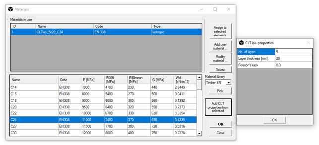
The creation of this material allows us to avoid the use of a layered cross section that is more complex to model and manage.
By indicating the number of layers, the thickness of the single layer and the Poisson's ratio to use, the program produces a new material, called CLTiso_5x20_C24, which exploits the Blass-Fellmoser equivalence for its definition.
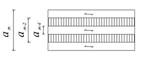
The original theory provides different formulations depending on the static scheme of the wall (floor panel, vertical wall, etc.). NextFEM Designer uses a simplified formulation for panels made up of layers of identical thickness, adaptable to all project situations.
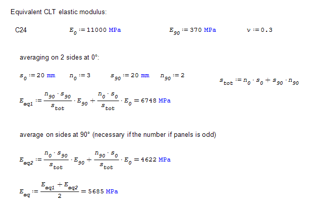
Let's see an example of calculating the equivalent elastic modulus:
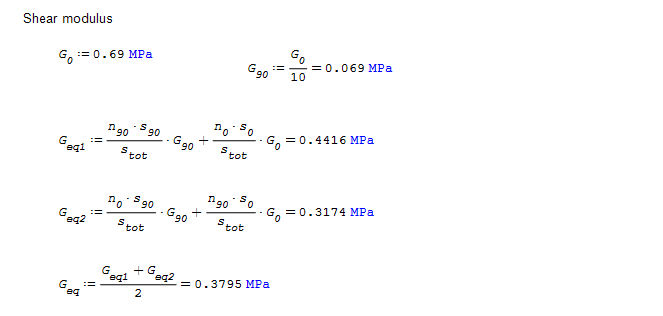
In the exact same way, the equivalent shear modulus G is obtained with the same relations:
Therefore, in our model the panels made up of 5 layers of 20mm each of C24 wood (E0=11 GPa and E90=370 MPa) will have an equivalent elastic modulus equal to E=5685 MPa.
Mesh of CLT panels
CLT panels can be modeled easily via the Edit / Mesh Tools / Add Wall command .
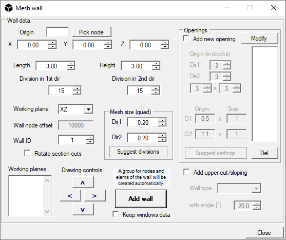
Simply do the following:
1. select a source node for the wall or enter its coordinates manually;
2. choose Length and Width, in the example both 3m, and the lying plane (XZ or YZ for vertical walls, XY for horizontal ones);
3. choose an appropriate size of the mesh in the two directions Dir1 and Dir2 . This operation is particularly important for calculating the stiffness of the springs representing the screws;
4. add any windows and press “Add wall” to see it drawn in the viewport.
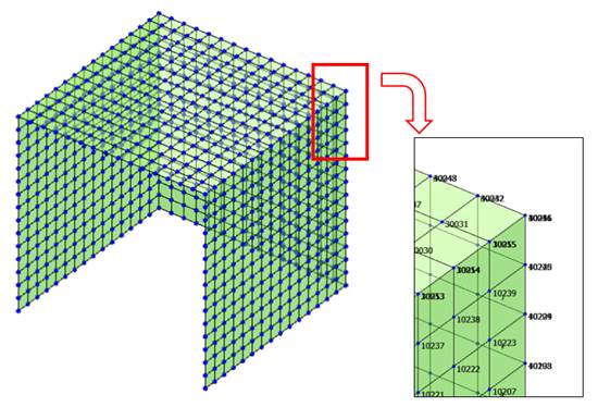
With this procedure, we model, for example, a set of walls as in the figure below. Note how the corner nodes of the walls are doubled: this will allow the installation of the springs.
Modeling of metal connections
The modeling of the mechanical behavior of metal connections is generally valid only in the non-linear field: think for example of hold-down, which reacts in traction with a stiffness depending on the nailing of the panel, while in compression with the contact stiffness between panel to panel or between panel and foundation. The latter is a much higher value than the tensile one, therefore it is necessary to find a single value, valid for linear analyses. Eurocode 5 comes to our aid, estimating the elastic stiffness Kser in §7.1 for a nail stressed in shear. Experimental investigations have highlighted how estimating the stiffness by multiplying Kser by the number of nails provides a higher value than the experimental one (i.e. obtained from laboratory tests) of the connection: this happens because in reality there are more elements in series which contribute to resistance in the connector and stiffness (plasticization of the connector, stability of the metal plates, etc.).
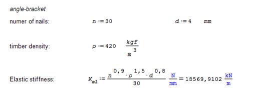
The shear stiffness for a metal angle with 30 nails d=4mm is calculated as:
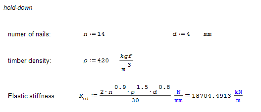
Similarly, the axial stiffness of a hold-down with 14 nails d=4mm can be estimated using the effective number of nails (here exemplified as n raised to the power of 0.9). It seems a good compromise to calculate the stiffness of these connectors as twice the stiffness provided by the formulas presented below, in order to consider compression in the linear field on a flat-rate basis.
CAUTION: the approach described could artificially alter the hierarchy of resistances, since the coefficient 2 chosen could excessively favor rocking of the wall at the expense of sliding. The designer should make the appropriate considerations. For a more accurate calculation, use a non-linear model.
Once these values have been obtained, we can set the springs representing the connections.
NextFEM Designer allows the creation of zero-length springs (for coincident nodes) that represent the stiffness provided by hold-downs, angles and screws, and on which to finally perform the resistance check. These springs are necessarily defined in the global axes of the model, since they have zero length.
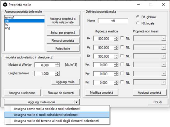
From the Assign / Spring Properties form we create:
- a spring called “hd” for its hold-down properties, with elastic stiffness Kz equal to 19000kN/m;
- a shear spring called “ang” with shear stiffnesses Kx=Ky=52000kN/m;
- a spring for the screws with the stiffness of a number of screws equal to the center distance of the mesh (e.g. 20cm => 1 screw = 900kN/m), in the 3 spatial directions.
Now simply select the (double) nodes affected by the springs with the selection rectangle and select the Add nodal springs / Assign springs to the selected coincident nodes command .
In this way, the assembly in the following figure is created, in which the creation of a box-like CLT structure is exemplified, connected to the ground using angles and hold-downs, and with screws between the walls and the attic.
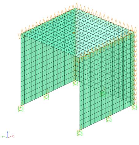
If, as in this case, the model does not include the foundations and is constrained to the ground, another dedicated command ( Add nodal springs / Assign as nodal spring to selected nodes ) will allow the insertion of corners and hds at the base, by doubling the knot, added knot interlocking constraint and spring insertion.
Conclusions part one
While taking into account the simplifications that linear field modeling imposes, the "component" model developed also allows control of the resistance hierarchy since, unlike macro-element models, the angular and hold-down response can be controlled separately.
Furthermore, the described approach adapts very well to the analysis of mixed structures (e.g. CLT super-elevations of existing buildings), also allowing the precise dimensioning of the anchorages to the pre-existing structure, which would not have been possible with drains from the walls distributed along their length.
Download the free resources! The files can be viewed with SMath Studio :
Calculation of the stiffness of X-Lam panels at Blass-Fellmoser
Calculation of the stiffness of metal connections for X-Lam
NextFEM Designer also supports native interfacing with SMath Studio via the NextFEM4SMath plugin .